
RYOBI RE180PL1 2HP Peak 10-Amp Plunge Router

GENERAL POWER TOOL SAFETY WARNINGS
WARNING
Read all safety warnings and all instructions. Failure to follow the warnings and instructions may result in electric shock, fire and/or serious injury.
Save all warnings and instructions for future reference. The term “power tool” in the warnings refers to your mains-operated (corded) power tool or battery-operated (cordless) power tool.
WORK AREA SAFETY
- Keep work area clean and well lit. Cluttered or dark areas invite accidents.
- Do not operate power tools in explosive atmospheres, such as in the presence of flammable liquids, gases or dust. Power tools create sparks which may ignite the dust or fumes.
- Keep children and bystanders away while operating a power tool. Distractions can cause you to lose control.
ELECTRICAL SAFETY
- Power tool plugs must match the outlet. Never modify the plug in any way. Do not use any adapter plugs with earthed (grounded) power tools. Unmodified plugs and matching outlets will reduce risk of electric shock.
- Avoid body contact with earthed or grounded surfaces such as pipes, radiators, ranges and refrigerators. There is an increased risk of electric shock if your body is earthed or grounded.
- Do not expose power tools to rain or wet conditions. Water entering a power tool will increase the risk of electric shock.
- Do not abuse the cord. Never use the cord for carrying, pulling or unplugging the power tool. Keep cord away from heat, oil, sharp edges or moving parts. Damaged or entangled cords increase the risk of electric shock.
- When operating a power tool outdoors, use an extension cord suitable for outdoor use. Use of a cord suitable for outdoor use reduces the risk of electric shock.
- If operating a power tool in a damp location is unavoidable, use a ground fault circuit interrupter (GFCI) protected supply. Use of a GFCI reduces the risk of electric shock.
PERSONAL SAFETY
- Stay alert, watch what you are doing and use com-mon sense when operating a power tool. Do not use a power tool while you are tired or under the influence of drugs, alcohol or medication. A moment of inattention while operating power tools may result in serious personal injury.
- Use personal protective equipment. Always wear eye protection. Protective equipment such as dust mask, non-skid safety shoes, hard hat, or hearing protection used for appropriate conditions will reduce personal injuries.
- Prevent unintentional starting. Ensure the switch is in the off-position before connecting to power source and/or battery pack, picking up or carrying the tool. Carrying power tools with your finger on the switch or energizing power tools that have the switch on invites accidents.
- Remove any adjusting key or wrench before turning the power tool on. A wrench or a key left attached to a rotating part of the power tool may result in personal injury.
- Do not overreach. Keep proper footing and balance at all times. This enables better control of the power tool in unexpected situations.
- Dress properly. Do not wear loose clothing or jewelry. Keep your hair, clothing and gloves away from moving parts. Loose clothes, jewelry or long hair can be caught in moving parts.
- If devices are provided for the connection of dust extraction and collection facilities, ensure these are connected and properly used. Use of dust collection can reduce dust-related hazards.
- Do not wear loose clothing or jewelry. Contain long hair. Loose clothes, jewelry, or long hair can be drawn into air vents.
- Do not use on a ladder or unstable support. Stable footing on a solid surface enables better control of the power tool in unexpected situations.
POWER TOOL USE AND CARE
- Do not force the power tool. Use the correct power tool for your application. The correct power tool will do the job better and safer at the rate for which it was designed.
- Do not use the power tool if the switch does not turn it on and off. Any power tool that cannot be controlled with the switch is dangerous and must be repaired.
- Disconnect the plug from the power source and/or the battery pack from the power tool before making any adjustments, changing accessories, or storing power tools. Such preventive safety measures reduce the risk of starting the power tool accidentally.
- Store idle power tools out of the reach of children and do not allow persons unfamiliar with the power tool or these instructions to operate the power tool. Power tools are dangerous in the hands of untrained users.
- Maintain power tools. Check for misalignment or bind-ing of moving parts, breakage of parts and any other condition that may affect the power tool’s operation. If damaged, have the power tool repaired before use. Many accidents are caused by poorly maintained power tools.
- Keep cutting tools sharp and clean. Properly main-tained cutting tools with sharp cutting edges are less likely to bind and are easier to control.
- Use the power tool, accessories and tool bits etc. in accordance with these instructions, taking into account the working conditions and the work to be performed. Use of the power tool for operations different from those intended could result in a hazardous situation.
SERVICE
- Have your power tool serviced by a qualified repair person using only identical replacement parts. This will ensure that the safety of the power tool is maintained.
- When servicing a power tool, use only identical re-placement parts. Follow instructions in the Maintenance section of this manual. Use of unauthorized parts or failure to follow Maintenance instructions may create a risk of shock or injury.
ROUTER SAFETY WARNINGS
- Hold power tool by insulated gripping surfaces, be-cause the cutter may contact its own cord. Cutting a “live” wire may make exposed metal parts of the power tool “live” and shock the operator.
- Use clamps or another practical way to secure and support the workpiece to a stable platform. Holding the work by your hand or against the body leaves it unstable and may lead to loss of control.
- Know your power tool. Read operator’s manual care-fully. Learn its applications and limitations, as well as the specific potential hazards related to this tool. Following this rule will reduce the risk of electric shock, fire, or serious injury.
- Always wear eye protection with side shields marked to comply with ANSI Z87.1. Following this rule will re-duce the risk of serious personal injury.
- Protect your lungs. Wear a face or dust mask if the operation is dusty. Following this rule will reduce the risk of serious personal injury.
- Protect your hearing. Wear hearing protection during extended periods of operation. Following this rule will reduce the risk of serious personal injury.
- Inspect tool cords periodically and, if damaged, have repaired at your nearest authorized service center. Constantly stay aware of cord location. Following this rule will reduce the risk of electric shock or fire.
- Check damaged parts. Before further use of the tool, a guard or other part that is damaged should
- be carefully checked to determine that it will operate properly and perform its intended function. Check for alignment of moving parts, binding of moving parts, breakage of parts, mounting, and any other conditions that may affect its operation. A guard or other part that is damaged should be properly repaired or replaced by an authorized service center. Following this rule will reduce the risk of shock, fire, or serious injury.
- Make sure your extension cord is in good condition. When using an extension cord, be sure to use one heavy enough to carry the current your product will draw. A wire gauge size (A.W.G.) of at least 14 is recommended for an extension cord 50 feet or less in length. A cord exceeding 100 feet is not recom-mended. If in doubt, use the next heavier gauge. The smaller the gauge number, the heavier the cord. An undersized cord will cause a drop in line voltage resulting in loss of power and overheating.
- Inspect for and remove all nails from lumber before using this tool. Following this rule will reduce the risk of serious personal injury.
- If the power supply cord is damaged, it must be re-placed only by the manufacturer or by an authorized service center to avoid risk.
- Save these instructions. Refer to them frequently and use them to instruct others who may use this product. If you loan someone this product, loan them these instructions also.
SYMBOLS
| The following signal words and meanings are intended to explain the levels of risk associated with this product. | ||
| SYMBOL | SIGNAL | MEANING |
 |
DANGER: | Indicates a hazardous situation, which, if not avoided, will result in death or serious injury. |
 |
WARNING: | Indicates a hazardous situation, which, if not avoided, could result in death or serious injury. |
 |
CAUTION: | Indicates a hazardous situation, that, if not avoided, may result in minor or moderate injury. |
| NOTICE: | (Without Safety Alert Symbol) Indicates information considered important, but not related to a potential injury (e.g. messages relating to property damage). | |
| Some of the following symbols may be used on this product. Please study them and learn their meaning. Proper interpretation of these symbols will allow you to operate the product better and safer. | ||
| SYMBOL | NAME | DESIGNATION/EXPLANATION |
 |
Safety Alert | Indicates a potential personal injury hazard. |
 |
Read Operator’s Manual |
To reduce the risk of injury, user must read and understand operator’s manual before using this product. |
 |
Eye Protection |
Always wear eye protection with side shields marked to comply with ANSI Z87.1. |
 |
Wet Conditions Alert |
Do not expose to rain or use in damp locations. |
| V | Volts | Voltage |
| A | Amperes | Current |
| Hz | Hertz | Frequency (cycles per second) |
| min | Minutes | Time |
| Alternating Current | Type of current | |
 |
No Load Speed | Rotational speed, at no load |
 |
Class II Construction | Double-insulated construction |
| … /min | Per Minute | Revolutions, strokes, surface speed, orbits etc., per minute |
ELECTRICAL
DOUBLE INSULATION
Double insulation is a concept in safety in electric power tools, which eliminates the need for the usual three-wire grounded power cord. All exposed metal parts are isolated from the internal metal motor components with protecting insulation. Double insulated tools do not need to be grounded.
WARNING:
The double insulated system is intended to protect the user from shock resulting from a break in the product’s internal insulation. Observe all normal safety precautions to avoid electrical shock.
NOTE: Servicing of a product with double insulation requires extreme care and knowledge of the system and should be performed only by a qualified service technician. For service, we suggest you return the product to your nearest authorized service center for repair. Always use original factory replace-ment parts when servicing.
ELECTRICAL CONNECTION
This product has a precision-built electric motor. It should be connected to a power supply that is 120 volts, AC only (normal household current), 60 Hz. Do not operate this product on direct current (DC). A substantial voltage drop will cause a loss of power and the motor will overheat. If the product does not operate when plugged into an outlet, double-check the power supply.
EXTENSION CORDS
When using a power tool at a considerable distance from a power source, be sure to use an extension cord that has the capacity to handle the current the tool will draw. An undersized cord will cause a drop in line voltage, resulting in overheating and loss of power. Use the chart to determine the minimum wire size required in an extension cord. Only round jacketed cords listed by Underwriter’s Laboratories (UL) should be used.
When working outdoors with a product, use an extension cord that is designed for outside use. This type of cord is designated with “W-A” or “W” on the cord’s jacket.
Before using any extension cord, inspect it for loose or exposed wires and cut or worn insulation. NOTE: AWG = American Wire Gauge
WARNING:
- Keep the extension cord clear of the working area. Position the cord so that it will not get caught on lumber, tools, or other obstructions while you are working with a power tool. Failure to do so can result in serious personal injury.
- Check extension cords before each use. If damaged replace immediately. Never use product with a damaged cord since touching the damaged area could cause elec-trical shock resulting in serious injury.
FEATURES
PRODUCT SPECIFICATIONS
Plunge Depth ……………… 2 in.
Collet …………………………. 1/2 in.
Adaptor ………………………. 1/4 in.
Horsepower ………………. 2
No Load Speed …………15,000-25,000/min (RPM)
Input ………..120 V, 60 Hz, AC only, 10 Amps
Net Weight …………… 8.5 lbs.
ASSEMBLY
WARNING:
- Do not use this product if it is not completely assembled or if any parts appear to be missing or damaged. Use of a product that is not properly and completely assembled or with damaged or missing parts could result in serious personal injury. Do not use this product if it is not completely assembled or if any parts appear to be missing or damaged. Use of a product that is not properly and completely assembled or with damaged or missing parts could result in serious personal injury.
- Do not attempt to modify this product or create accessories or attachments not recommended for use with this product. Any such alteration or modification is misuse and could result in a hazardous condition leading to possible serious personal injury.
If any parts are damaged or missing, please call 1-800-525-2579 for assistance.
OPERATION
WARNING:
- Do not allow familiarity with tools to make you care-less. Remember that a careless fraction of a second is sufficient to inflict serious injury.
- Always wear eye protection with side shields marked to comply with ANSI Z87.1, along with hearing protection. Failure to do so could result in objects being thrown into your eyes and other possible serious injuries.
- Do not use any attachments or accessories not recommended by the manufacturer of this tool. The use of attachments or accessories not recommended can result in serious personal injury.
- Do not use bits with undersized shanks. Undersized shanks will not tighten properly and could be thrown from the tool causing injury.
- If you are changing a bit immediately after use, be careful not to touch the collet nut, bit, or collet with your hands or fingers. You will get burned because of the heat buildup from cutting. Always use the wrench provided.
- If the collet nut is not securely tightened, the bit may detach during use, causing serious personal injury.
- Bit continues to rotate after the router has been turned off. To avoid injury, wait until the bit has come to a complete stop before removing router from the workpiece.
- Do not use bits which are larger than 2-1/4 in. Never use bits which are larger in diameter than the opening in the router subbase. These situations could cause possible loss of control or create other hazardous conditions that could cause possible serious personal injury.
CAUTION:
To prevent damage to the spindle or spindle lock, always allow motor to come to a complete stop before engaging the spindle lock.
APPLICATIONS
You may use this tool for the purposes listed below:
- Rout grooves, carve designs, mortise door jambs, and create joints in wood and wood products
- Cabinet making, routing counter tops, and finishing work in wood and wood products
INSTALLING/REMOVING BITS
- Unplug the router.
- Remove chip shield from router base by pushing two sides together and removing from base.
- Depress spindle lock.
- Place the wrench provided through front of router base onto collet nut and turn counterclockwise to loosen.
- Install bit once collet nut is loose. If changing bits, bit will easily slip from collet after loosening collet nut.
- Insert shank of bit until shank bottoms out, then pull it out 1/16 in. to allow for expansion when the bit gets hot.
- Tighten the collet nut securely by turning clockwise with the wrench provided.
- Release spindle lock.
- Replace chip shield.
To remove the bit:
- Place the wrench provided through front of router base onto collet nut and turn counterclockwise to loosen.
- Loosen the collet nut and remove the bit.
- Release the spindle lock.
INSTALLING/REMOVING THE 1/4 in. ADAPTOR
The collet is machined to precision tolerances to fit bits with 1/2 in. diameter shanks. To use bits with 1/4 in. diameter shanks, insert the 1/4 in. adaptor into the 1/2 in. collet.
- Unplug the router.
- Remove chip shield from router base by pushing two sides together and removing from base.
- Depress spindle lock.
- Place the wrench provided through front of router base onto collet nut and turn counterclockwise to loosen.
- Install adaptor once collet nut is loose.
- Insert 1/4 in. shank bit, then tighten the collet nut securely by turning clockwise with the wrench provided.
- Release spindle lock.
- Replace chip shield.
To remove the adaptor:
- Place the wrench provided through front of router base onto collet nut and turn counterclockwise to loosen.
- Loosen the collet nut and remove the adaptor and bit.
- Release the spindle lock.
SELECTING DEPTH OF CUT
Proper depth of cut depends on several factors: the horse-power of the router motor, the type of bit, and the type of wood. A lightweight, low horsepower router is designed for making shallow cuts; a router with higher horsepower is designed for deeper cuts. Small bits, such as veining bits with 1/16 in. cutting diameters, are designed to remove only small amounts of wood. Large bits, such as straight-flute bits, remove larger amounts of wood and make deeper cuts in soft woods, such as white pine.
Choose a depth of cut that will not place excessive strain on the router motor. If you need extra force or the motor speed slows down considerably, turn off the router and reduce the depth of cut. Then, make the cut in two or more passes.
When routing a groove that is too deep to safely cut in one pass, make the cut in several passes. We recommend that cuts be made at a depth not exceeding 1/8 in. and that several passes be made to reach deeper cuts.
TO ADJUST DEPTH OF CUT
- Unplug the router.
- Raise bit by unlocking plunge lock lever.
- Adjust hex nuts on threaded post until bit is inside router subbase.
- Place router on a flat surface.
- Lower router until tip of bit barely touches flat surface.
- Lock plunge lock lever to position bit at “zero” depth of cut.
- Adjust hex nuts until they come in contact with stop flange. This will provide a position stop at “zero” depth of cut.
- Make sure the hex nuts are securely tightened against each other.
- Rotate depth stop to desired position, loosen lock knob and adjust stop bar until it touches depth stop.
- Slide zero reset indicator up or down the scale on stop bar until red line on zero reset indicator aligns with a desired reference point. For example, align red line with 1 in. mark on the scale.
- Lift stop bar to obtain desired depth of cut. For example, if setting 1/8 in. depth of cut, the zero reset indicator will move 1/8 in. from the 1 in. reference point.
- Tighten lock knob securely.
- Position the router so that the bit can extend below the subbase for desired depth setting.
- Unlock plunge lock lever.
- Grasp handles and lower router until stop bar contacts depth stop.
- Lock plunge lock lever to position bit at desired depth of cut.
ZERO RESET INDICATOR
The zero reset indicator allows you to use the scale pro-vided on the housing to make quick depth of cut changes to existing depth of cut settings. Simply choose a reference point on the scale and slide the zero reset indicator up or down the scale the distance required for new depth of cut. Then change stop bar position by loosening lock knob and adjusting stop bar until red line on zero reset indicator moves back to reference point. Tighten lock knob securely to lock stop bar in new position. The bit position will now increase or decrease the exact distance the stop bar was adjusted.
NOTE: Each mark on the inch scale indicates 1/16 in.
ACCU-STOP™ MICRO-ADJUSTABLE DEPTH STOP
- The ACCU-STOP™ Micro-Adjustable Depth Stop is located on the base of your router and makes it possible to make deep or heavy cuts in successive passes. Alignment marks make depth of cut changes quick and easy.
- A preset cutting depth is achieved by plunging router until stop bar comes in contact with depth stop. The micro- adjusting feature provides alignment marks at each 90° rotation of the depth stop knob. Each 90° rotation of the knob changes depth of cut setting 1/64 in.
- A complete 360° rotation of the knob changes the depth of cut setting 1/16 in.
- The ACCU-STOP™ Micro-Adjustable Depth Stop provides for depth of cut changes to be made from 0 to 1/2 in. from the initial setting of the stop bar. This initial setting of the stop bar can be “zero” depth of cut, or it can be any depth of cut setting that you choose as a starting point for a particular job to be performed.
To use the ACCU-STOP™ Micro-Adjustable Depth Stop:
- Unplug the router.
- Loosen lock knob and raise stop bar.
- Rotate depth stop until the highest depth stop is aligned with the stop bar.
- Raise bit by unlocking plunge lock lever.
- Place router on flat surface, and lower router until tip of bit barely touches flat surface.
- Lock plunge lock lever to position bit at “zero” depth of cut.
- Lower stop bar against depth stop, then tighten lock knob securely. The highest stop now becomes the “zero” depth of cut setting.
SWITCH
The router features a soft start which allows for a gradual increase in speed from 0 r/min. to the variable speed dial setting. For example, if the router is set at 15,000 r/min. at the time it is switched off and is then activated again, the motor is designed to gradually rev up to that speed instead of starting out at the full 15,000 r/min.
To turn the router on, push the switch to the ( I ), or ON position. Return the switch to the ( O ), or OFF position when routing operation is finished.
VARIABLE SPEED CONTROL SELECTOR
The router has a variable speed control selector designed to allow operator control of speed and torque limits. You can make speed selections best suited to the type of cut, the material being cut, and the size of bit being used. The variable speed control selector allows you to adjust router speed from 15,000 to 25,000 r/min. There is a six-step scale (A to F) on the variable speed control selector. To increase the speed and torque of the router, turn the variable speed control selector to a higher setting (F). Turn to a lower setting to decrease speed and torque.
NOTE:
- If you do not want to use the variable speed control selector, turn it to the highest possible setting, and the feature will not be active.
- The speed selection chart shown gives suggested speed settings based on the diameter of the bit and the type of material being routed.
- We suggest that you practice with the variable speed feature of the router before installing a bit and making cuts in wood.
| SPEED SELECTION CHART | ||||
| MATERIAL | BIT SIZE | |||
| 1/4 | 3/8 | 1/2 | 3/4 | |
| SOFT | E-F | D-E | A-B | A |
| MEDIUM | D-E | C-D | A | A |
| HARD | C-D | B-C | A | A |
| VERY HARD | D-E | C-D | C-D | B-C |
OPERATING THE ROUTER
When routing straight cuts across a workpiece, clamp a straight edge to the workpiece to use as a guide.
Position the straight edge parallel to the line of cut and offset the distance between the cutting edge of the bit and the edge of the router base. Hold the router base against the straight edge and rout the groove.
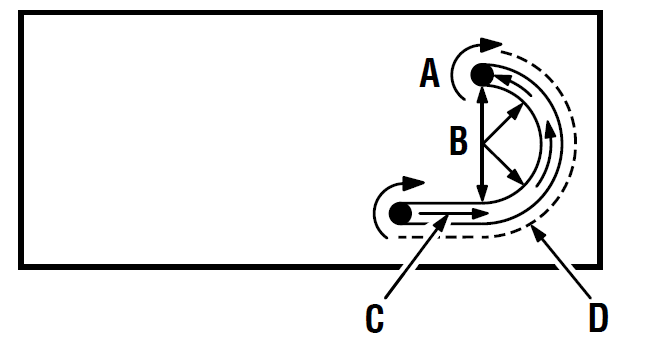
When routing a groove wider than the diameter of the bit, clamp a straight edge on both sides of the cut lines. Position both guides parallel to the desired line of cut and spaced equal distances from the desired edges of the groove. Rout along one guide then reverse direction and rout along the other guide. Clean out any remaining waste in the center of the groove.
When routing a groove, the travel should be in a direction that places the guide you are using at the right-hand side. When the guide is positioned as shown in the “guide inside” illustration tool travel should be from left to right and counterclockwise around curves. When the guide is positioned as shown in the “guide outside” illustration tool travel should be from right to left and clockwise around curves. If there is a choice, the first setup is generally the easier to use. In either case, the sideways thrust you use is against the guide.
INTERNAL ROUTING
- Tilt router and place on workpiece without the bit contacting the workpiece.
- Turn the router on and let the motor build up to full speed.
- Gradually feed bit into the workpiece until the subbase is level with the workpiece.
- Upon completion of the cut, turn the router off and let the bit come to a complete stop before removing the router from the workpiece.
EDGE ROUTING
- Clamp a straight edge to the workpiece as a guide.
- Place the router on the edge of the workpiece without the bit contacting the workpiece.
- Turn router on and let the motor build up to full speed.
- Gradually feed the bit into the workpiece using the clamped straight edge as a guide.
- Upon completion of the cut, turn the router off and let the bit come to a complete stop before removing the router from the workpiece.
WARNING:
Do not use large router bits for freehand routing. Use of large router bits when freehand routing could cause loss of control or create other hazardous conditions that could result in personal injury. If using a router table, large bits should be used for edging only.
FREEHAND ROUTING
When used freehand, the router becomes a flexible and versatile tool. This flexibility makes it possible to easily rout signs, relief sculptures, etc. When freehand routing:
- Draw or layout the pattern on the workpiece.
- Choose the appropriate bit.
NOTE: A core box or V-groove bit is often used for routing letters and engraving objects. Straight bits and ball mills are often used to make relief carvings. Veining bits are used to carve small, intricate details.
- Rout the pattern in two or more passes. Make the first pass at 25% of the desired depth of cut. This will provide better control as well as being a guide for the next pass.
NOTE: Do not rout deeper than 1/8 in. per pass.
EDGING WITH PILOT BIT
The arbor-type bits with pilots are excellent for quick, easy, edge shaping of any workpiece edge that is either straight or curved at a curvature as great or greater than the radius of the bit to be used. The pilot prevents the bit from making too deep a cut; and holding the pilot firmly in contact with the workpiece edge throughout prevents the cut from becoming too shallow.
Whenever the workpiece thickness together with the desired depth of cut (as adjusted by router depth setting) are such that only the top part of the edge is to be shaped (leaving at least a 1/16 in. thick uncut portion at bottom), the pilot can ride against the uncut portion, which serves to guide it. However, if the workpiece is too thin or the bit set too low so that there will be no uncut edge to ride the pilot against, an extra board to act as a guide must be placed under the workpiece. This “guide” board must have exactly the same contour straight or curved as the workpiece edge. If it is positioned so that its edge is flush with the workpiece edge, the bit will make a full cut (in as far as the bit radius). On the other hand, if the guide is positioned as shown in figure 13 (out from the workpiece edge), the bit will make less than a full cut — which will alter the shape of the finished edge.
NOTE: Any of the piloted bits can be used without a pilot for edge shaping with guides, as preceding. The size (diameter) of the pilot that is used determines the maximum cut width that can be made with the pilot against the workpiece edge (the small pilot exposes all of the bit; the large one reduces this amount by 1/16 in.).
DIRECTION OF FEED AND THRUST
The router motor and bit revolve in a clockwise direction. This gives the tool a slight tendency to twist in a counterclockwise direction, especially when the motor revs up.
Feed the router into the workpiece from left to right. When fed from left to right, the rotation of the bit pulls the router against the workpiece. If fed in the opposite direction, the rotation of the spinning bit will tend to throw the router away from the workpiece causing kickback. This could cause you to lose control of the router.
Because of the high speed of bit rotation during a proper feeding operation, there is very little kickback under normal conditions. However, if the bit strikes a knot, hard grain, or foreign object that affects the normal progress of the cutting action, there will be a slight kickback. The direction of kickback is always in the direction opposite bit rotation. This will affect the trueness of the cut.
To guard against kickback, plan the setup and direction of feed so that you will always be thrusting the tool in the same direction that the leading edge of the bit is moving. The thrust should be in a direction that keeps the sharp edges of the bit continuously biting straight into new (uncut) wood.
NOTE: For best results, make sure to take enough time to set up for cutting. While cutting, make sure to use the proper rate of feed.
PROPER RATE OF FEED
Professional routing depends upon careful setup and proper rate of feed which is learned through practice and use. The proper rate of feed is dependent upon:
- hardness and moisture content of the workpiece
- depth of cut
- cutting diameter of the bit
When cutting shallow grooves in soft woods such as pine, a faster rate of feed can be used. When making cuts in hardwoods such as oak, a slower rate of feed is required.
Several factors will help you select the proper rate of feed.
- Choose the rate that does not slow down the motor.
- Choose the rate at which the bit advances firmly and surely to produce a continuous spiral of uniform chips or a smooth edge.
- Listen to the sound of the motor. A high-pitched sound means you are feeding too slowly. A strained, lower pitched sound signals force feeding.
- Check the progress of each cut. Too slow feeding can cause the router to take off in a wrong direction from the intended line of cut. Force feeding increases the strain of holding the tool and results in loss of speed.
- Notice the chips being produced as you cut. If the router is fed too slowly, it will scorch or burn the wood. If fed too fast, it will take large chips out of the wood and leave gouge marks.
Test a cut on a scrap piece of the workpiece before you begin. Always grasp and hold the router firmly with both hands.
If you are making a small diameter, shallow groove in soft, dry wood, the proper feed rate may be determined by the speed at which you can travel the router along the guide line. If the bit is a large one, the cut is deep, or the workpiece is hard to cut, the proper feed may be a very slow one. A cross grain cut may require a slower pace than an identical with grain cut in the same workpiece.
FEEDING TOO FAST
Clean, smooth routing and edge shaping can be done only when the bit is revolving at a relatively high speed and is taking very small bites to produce tiny, cleanly severed chips. If you force the router to move forward too fast, the RPM of the bit becomes slower than normal in relation to its forward movement. As a result, the bit must take bigger bites as it revolves. Bigger bites mean bigger chips and a rougher finish. Also, because bigger bites require more power, the router motor may become overloaded.
Under extreme force-feeding conditions, the relative RPM of the bit can become so slow and the bites it has to take so large that chips will be partially knocked off (rather than fully cut off). This causes splintering and gouging of the workpiece.
The router is an extremely high-speed tool, and will make clean, smooth cuts if allowed to run freely without the overload of a forced feed. You can always detect force feeding by the sound of the motor. Its high-pitched whine will sound lower and stronger as it loses speed. Also, the strain of holding the tool will be noticeably increased.
FEEDING TOO SLOWLY
It is possible to spoil a cut by moving the router forward too slowly. When you advance the router into the work too slowly, the revolving bit does not dig into new wood fast enough to take a bite; instead, it merely scrapes away sawdust-like particles. Scraping produces heat, which can glaze, burn, or mar the cut and in extreme cases, can overheat the bit, destroying its hardness.
When the bit is scraping instead of cutting, controlling the router is more difficult. With practically no load on the motor, the bit revolves at close to top RPM, and has a much greater than normal tendency to bounce off the sides of the cut (especially if the wood has a pronounced grain with hard and soft areas). As a result, the cut produced may have rippled, instead of straight, sides.
Feeding too slowly can also cause the router to take off in a wrong direction from the intended line of cut. Always grasp and hold the router firmly with both hands when routing.
You can detect when you are feeding the router too slowly by the runaway, high-pitched sound of the motor or by feeling the wiggle of the bit in the cut.
DEPTH OF CUT
Depth of cut is important because it affects the rate of feed that, in turn, affects the quality of the cut and the possibility of damage to the tool’s motor and bit.
A deep cut requires a slower feed than a shallow one. A cut that is too deep will slow the feed so that the bit is scraping rather than cutting. A too deep cut can cause smaller bits to be broken off. Bits that are 1/16 in. in diameter are easily broken off when subjected to too much side thrust. A large enough bit is not likely to break, but attempting a cut that is too deep may result in a rough cut, and it may be difficult to guide and control the bit as desired. It is recommended that you do not exceed 1/8 in. depth of cut in a single pass, regardless of the bit size or the softness or condition of the workpiece.
To make deeper cuts, make as many successive passes as needed, lowering the bit 1/8 in. for each new pass. To save time, perform all the cutting necessary at one depth setting before lowering the bit for the next pass. This will insure a uniform depth when you complete the final pass.
NOTE: Do not remove more than 1/8 in. in a single pass. Excessive depth of cut can result in loss of control and the possibility of serious personal injury.
ROUTER TABLE
When mounting the router to a router table, use the two screws supplied. These screws will secure the router to the router table properly. Use of any other type and size screws could result in an accident causing possible serious injury. Do not use 8 mm screws.
ADJUSTMENTS
PLUNGE LOCK LEVER
After extended use, the plunge lock may wear. If this hap-pens, you can easily adjust the lever.
- Unplug the router.
- Make sure lever is in locked position.
- Remove the screw supporting the plunge lock lever.
- Remove the lever.
- Place the lever back in the original locked position.
- Replace the screw.
- Check for free plunge with lever rotated to unlocked position. If router does not plunge freely, reposition lever.
MAINTENANCE
WARNING:
Before performing any adjustment, make sure the tool is unplugged from the power supply and the switch is in the OFF ( O ) position. Failure to heed this warning could result in serious personal injury.
WARNING:
- When servicing, use only identical replacement parts. Use of any other parts could create a hazard or cause product damage.
- Always wear eye protection with side shields marked to comply with ANSI Z87.1, along with hearing protection. Failure to do so could result in objects being thrown into your eyes and other possible serious injuries.
- Do not at any time let brake fluids, gasoline, petroleum-based products, penetrating oils, etc., come in contact with plastic parts. Chemicals can damage, weaken or destroy plastic which could result in serious personal injury.
GENERAL MAINTENANCE
Avoid using solvents when cleaning plastic parts. Most plastics are susceptible to damage from various types of commercial solvents and may be damaged by their use. Use clean cloths to remove dirt, dust, oil, grease, etc. Electric tools used on fiberglass material, wallboard, spackling compounds, or plaster are subject to accelerated wear and possible premature failure because the fiberglass chips and grindings are highly abrasive to bearings, brushes, commutators, etc. Consequently, we do not recommended using this tool for extended work on these types of materials. However, if you do work with any of these materials, it is extremely important to clean the tool using compressed air.
LUBRICATION
All of the bearings in this tool are lubricated with a sufficient amount of high grade lubricant for the life of the unit under normal operating conditions. Therefore, no further lubrication is required.
POWER SUPPLY CORD REPLACEMENT
If replacement of the power supply cord is necessary, this must be done by an authorized service center in order to avoid a safety hazard.
CLEANING THE BITS
Get faster more accurate cutting results by keeping bits clean and sharp. Remove all accumulated pitch and gum from bits after each use. When sharpening bits, sharpen only the inside of the cutting edge. Never grind the outside diameter. When sharpening the end of a bit, be sure to grind the clearance angle the same as originally ground.
CLEANING THE COLLET
From time to time, it becomes necessary to clean the collet and collet nut. To do so, simply remove collet nut from collet and clean the dust and chips that have collected. Then return collet nut to its original position.
BRUSH ASSEMBLIES
The router has externally accessible brush assemblies that should periodically be checked for wear.
To replace brushes:
- Unplug the router.
- Remove brush cap with a screwdriver. Brush assembly is spring loaded and will pop out when you remove brush cap.
- Remove brush assembly (brush and spring).
- Check for wear. If worn, always replace in pairs. Do not replace one side without replacing the other.
- Reassemble using new brush assemblies. Make sure curvature of brush matches curvature of motor and that brush moves freely in brush tube.
- Make sure brush cap is oriented correctly (straight) and replace.
- Tighten brush cap securely. Do not over torque.
FIGURES

- A Zero reset indicator
- B Accu-Stop™ micro-adjustable depth stop
- C 1/4 in. adaptor
- D Chip shield
- E Spindle lock
- F Variable speed control selector

- A Collet nut
- B Collet
- C 1/4 in. adaptor

- A Spindle lock
- B To loosen collet nut
- C To tighten collet nut
- D Wrench
- E Bit
- F Collet nut

- A To lock
- B To unlock
- C Hex nuts
- D Bit inside subbase
- E Plunge lock lever

- A Scale
- B Lock knob
- C Stop bar
- D Tip of bit touching workpiece = zero depth to cut

- A Zero reset indicator with red line

- A Scale
- B Zero reset indicator with red line
- C Lock knob
- D Stop bar
- E Accu-Stop™ micro-adjustable depth stop

- A Each 90° rotation equals 1/64 in. change in depth of cut
- B Each complete 360° rotation of depth stop

- A Motor housing
- B On
- C Off
- D Switch

- A To increase speed
- B To decrease speed
- C Variable speed control selector
- D -Speed selection sight window

- A Workpiece

- A Workpiece
- B Straight edge
- C Clamp

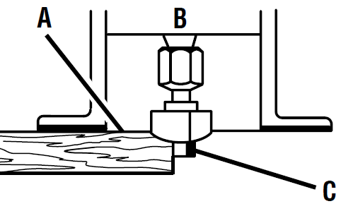
- TOP EDGE SHAPING

- WHOLE EDGE SHAPING
- A Work
- B Router
- C Pilot
- D Guide

- [6,4 à 25,4 mm
- [6,4 a 25,4 mm
- A Proper cutting sequence
GUIDE OUTSIDE

GUIDE INSIDE
- A Bit rotation
- B Thrust
- C Feed
- D Guide

TOO FAST

TOO SLOW

- A Depth of cut
- B Width of cut

- A 1st pass
- B 2nd pass

- A Plunge lock lever
- B To loosen
- C To tighten
- D Screw

- A Brush assembly
- B Brush cap
To request service, purchase replacement parts, locate an Authorized Service Center or obtain Customer or Technical Support:
Visit www.ryobitools.com or call 1-800-525-2579
If any parts or accessories are damaged or missing, do not return this product to the store. Call 1-800-525-2579 for immediate service.
Please obtain your model and serial number from the product data plate.
This product is covered under a 3-year limited Warranty. Proof of purchase is required.
MODEL NUMBER _______________ SERIAL NUMBER ____________________________
Model number on product may have additional letters at the end. These letters designate manufacturing information and should be provided when calling for service.
RYOBI is a registered trademark of Ryobi Limited and is used pursuant to a license granted by Ryobi Limited.